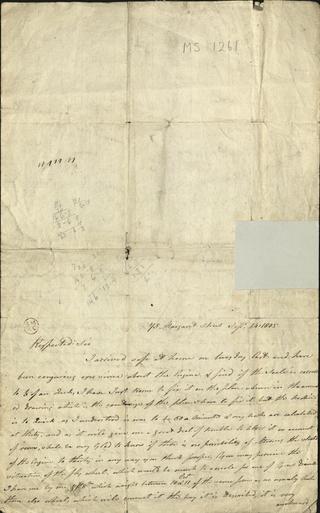
Letter from Henry Maudslay to Mr Matthew Murray, Engineer
'The aerial candidates...', an aeronautical play
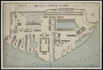
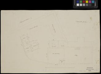
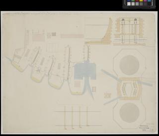
Ground plan of Her Majesty's Dockyard in Plymouth
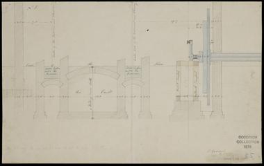
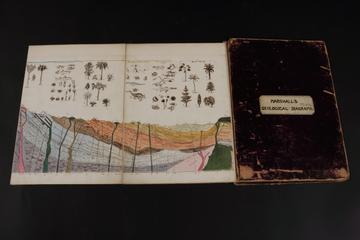
Drawing of engine house, cross section
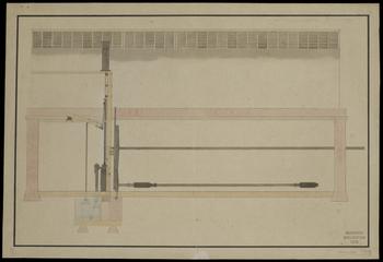
Design for the steam engine for metal mills, longitudinal section of foundry

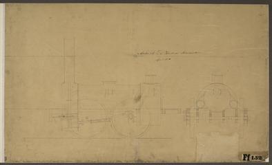
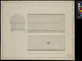
Drawing of engine house, section of boiler seating and stokehole
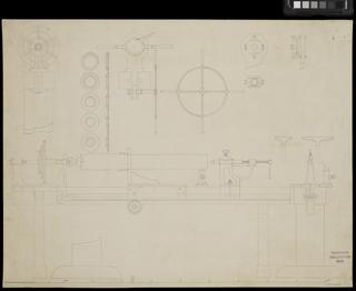
Drawing of treenail and coak making lathe
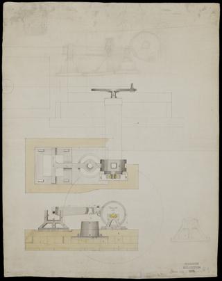
Drawing of forge hammer from Birmingham by Robert Roberts
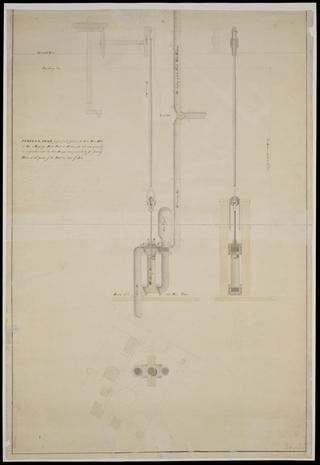
Drawing of forcing pump proposed to be fixed in the salt water well in His Majesty's Dockyard at Portsmouth
Ground plan of building of Kings Mills at Portsmouth

Copy sketch of Mr Heppenstall's spinning frame for rope yarn
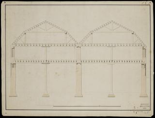
Section of building over Coal Yard, Metal Mills, Portsmouth
An edition of 'The Photogram' journal vol. 2 no. 17
Drawing of Locomotive Engine for the Stockton and Darlington Railway
Mohawk and Hudson Locomotive drawing
Railway Signal Volume 3 (1885)

Design for rebuilding of Albion Mills fire proof, transverse section

Design for an atmospherical engine steam cylinder with air pump, condenser and winding machinery
Copy plan of part of Plymouth Dockyard showing pump houses, drains and dock
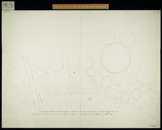
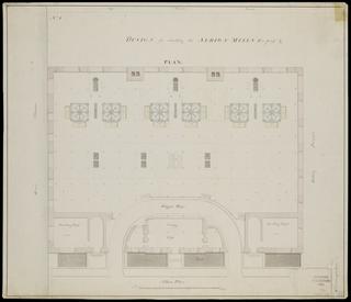
Plan of left half of middle group for General Plan 28.
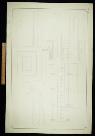
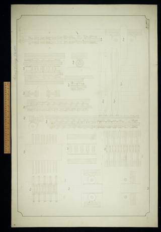
Small planing machine. Sheet 1.
Drawing depicting a portable steam engine

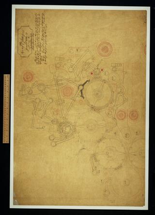
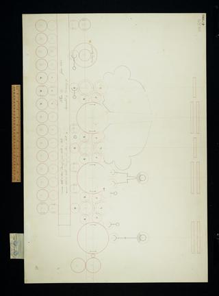
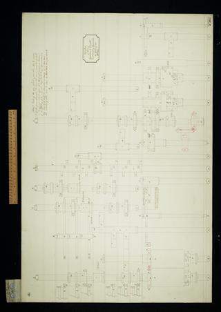
Plan of operation and variable card counting apparatus. Suited to Plans 28 and 28a.
![Pamphlet entitled ‘A Further Report, on the Intended Rail or Tram Road, from Stockton, by Darlington, to the collieries, with a branch to Yarum [sic]’](https://coimages.sciencemuseumgroup.org.uk/525/900/large_thumbnail_rais_3_6_1_000.jpg)
Pamphlet entitled ‘A Further Report, on the Intended Rail or Tram Road, from Stockton, by Darlington, to the collieries, with a branch to Yarum [sic]’

Plan of a proposed alteration to locomotive engines
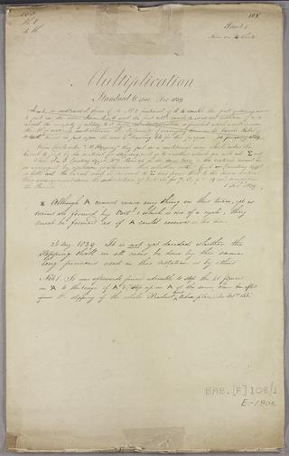
Multiplication. Sheet 1 of 4.
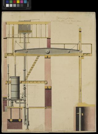
Drawing depicting elevation of the engine and longitudinary section of the engine house for an atmospherical steam engine
Plan 27. This was superseded by Drawing 93. Linear arrangement.

Plan and elevation of sundry parts in the upper cages of left half of middle group.
Platform raising apparatus. Sheet 33.

Verticals for approximative division. Sheet 2 of 4.
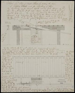
Sketch of a pair of small shears for cutting the edges of copper sheets used for the sheating of ships

Long pinions in the position for adding. Adding wheels and short pinions behind long pinions.
![Drawing of Tender for the Magnet Loco Engine, No. 108 Two end sections showing wheels, axle boxes and brake arrangement, [presumably for new tender-patent drawing]](https://coimages.sciencemuseumgroup.org.uk/83/229/large_thumbnail_19124_3.jpg)
Drawing of Tender for the Magnet Loco Engine, No. 108 Two end sections showing wheels, axle boxes and brake arrangement, [presumably for new tender-patent drawing]
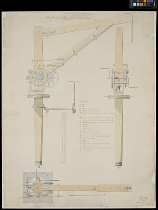
Elevation and plan of a crane capable of lifting from five to six tons
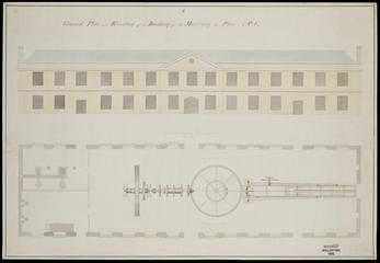
Ground plan and elevation of a building for the machinery used for making block and pullies at Dunsterville Manufactory
Drawings of boiler for 56 Horse steam engine at the Metal Mills, Portsmouth

Elevation of parts of middle group drawn in plan on No. 127.
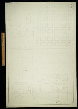
Elevation of parts of the card counting apparatus for operation and variable cards.
An edition of 'The Photogram' journal vol. 5 no. 50
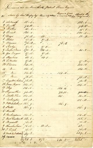
A statement of the premiums owned on Trevithick's patent for high pressure steam engines
Grouping arrangement. Abandoned end April 1835.

Method of grouping for the large machine.

Plan of the left half to middle group for General Plan 28.
Sections of framing and racks. Sheet 6.

Verticals for approximative division. Sheet 4 of 4.
Design for rebuilding of Albion Mills fire proof
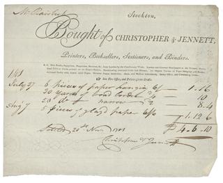
Invoice regarding stationary purchases
